
Lab 2
Contents
- Case-study
- Exercise 1:
- Exercise 2:
- Multi-Threading in Micropython
- Exercise 3
- Task 1
- Collecting the Labelled Data
- Google Co-lab and analysis
Case-study
You are appointed as an IoT Engineer at a company which manufactures presence detection sensor systems. These sensors are integrated into number of use-cases:
- desk space management, i.e. if someone is sitting on the desk it can be detected as occupied;
- parking slot, i.e., if car is parked over sensor installed in parking bay, then it can be declared as busy;
- smart parcel boxes, i.e., the parcel box is fitted with light source when interrupted with a parcel being added to box, sensor can detect the presence of parcel. Our hero LK, also uses the solution you will develop to detect if somebody has stepped into geo-fenced area of the base. To this end, your first task is to write code which can allow your hardware platform to detect light levels.
In your lab kit, you have Grove Light Sensor [Documentation here] . This is what we will employ for the rest of this lab.
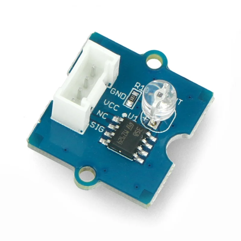
Definition
The grove light sensor is simply a light dependent resistor (LDR) or photo-resistor. It changes its resistance proportional to the intensity of ambient light. The signal is amplified using an on-board operational amplifier. In this case LM358 is used as an Op-amp. The principle of operation of LDR is very simple. If you have a known reference resistance, say , the variation in LDR resistance (say ) can be measured using voltage divider principle. Refer to the figure shown below. It is obvious that at ADC pin you will be getting a voltage which can be given by:
Technically, there is only one unknown as other quantities are either known/fixed or can be measured. So its easy to calculate the unknown value. Since we want to isolate the input pin from the voltage divider itself, an op-amp can serve as a buffer. Isolating its inputs and outputs. That is why having an op-amp at provides a good design.

Exercise 1:
Note
Our first task is to write code to read ADC values from the Grove Light Sensor.
Step 1: Revisit the Grove Shield Schematic Page [Click here] . Find out the A0 port this is ADC 0 of the board.
Step 2: Now complicated bit, need to find mapping between A0 and the actual pin number. If we were in Arduino IDE using C, we can use A0 directly. Sadly not in Micropython envirnoment, we need to find actual pin number. So let us go back to schematic [Click here] and locate which pin is labelled as A0. Its GPI01 as shown in the schematic diagram.
Step 3: Now using this knowledge, let us write code to read the analog input from GPIO1.
Step 4: Before we do anything, let us create a new folder on desktop. Let us call it Lab 2.
Step 5: Navigate to this folder from Thonny. Inside this create "main.py". Our code will sit here. Today, we will be creating several other files in this folder.
Step 6: Following is the example code which uses GPIO1, to read ADC value.
import time
from machine import Pin, ADC

# Initialize the analog input on pin 2 (corresponds to A0)
analog_in = ADC(Pin(1))
analog_in.atten(ADC.ATTN_11DB)  # Configure the input range (0-3.6V)

def get_voltage(pin):
    # Convert the raw ADC value to voltage
    return (pin.read() / 4095) * 3.3

while True:
    # Read the raw analog value
    raw_value = analog_in.read()
    # Convert the raw value to voltage
    voltage = get_voltage(analog_in)

    # Print the raw value and voltage to the serial console
    print("[Light] Raw value: {:5d} Voltage: {:.2f}V".format(raw_value, voltage))

    # Delay for a short period of time before reading again
    time.sleep(1)
Something to Ponder
From the micropython and ESP32S3 documentation find out the resolution of ADC, i.e., how many bits are being used for representing input voltage. Also find out why ATTN_11DB is needed to map to correct voltage range.
Exercise 2:
Now that you know how to read the ADC value. Its time to use this to control an output. You can collect the LED Bar from the lab assistants for this lab. The Grove LED Bar is a 10 segment LED gauge bar and an MY9221 LED controlling chip. In order to use the bar, we need either pre-built library for MY9221 or need to write one ourselves. Thankfully this is available as open source contribution.
Step 1: Go to your folder where main.py is located. You may already be here as you ran the previous programme.
Step 2: Copy following code in a new file and save it as my9221.py in the same folder.
"""
MicroPython MY9221 LED driver
https://github.com/mcauser/micropython-my9221

MIT License
Copyright (c) 2018 Mike Causer

Permission is hereby granted, free of charge, to any person obtaining a copy
of this software and associated documentation files (the "Software"), to deal
in the Software without restriction, including without limitation the rights
to use, copy, modify, merge, publish, distribute, sublicense, and/or sell
copies of the Software, and to permit persons to whom the Software is
furnished to do so, subject to the following conditions:

The above copyright notice and this permission notice shall be included in all
copies or substantial portions of the Software.

THE SOFTWARE IS PROVIDED "AS IS", WITHOUT WARRANTY OF ANY KIND, EXPRESS OR
IMPLIED, INCLUDING BUT NOT LIMITED TO THE WARRANTIES OF MERCHANTABILITY,
FITNESS FOR A PARTICULAR PURPOSE AND NONINFRINGEMENT. IN NO EVENT SHALL THE
AUTHORS OR COPYRIGHT HOLDERS BE LIABLE FOR ANY CLAIM, DAMAGES OR OTHER
LIABILITY, WHETHER IN AN ACTION OF CONTRACT, TORT OR OTHERWISE, ARISING FROM,
OUT OF OR IN CONNECTION WITH THE SOFTWARE OR THE USE OR OTHER DEALINGS IN THE
SOFTWARE.
"""

from time import sleep_ms
from machine import Pin

class MY9221:
    def __init__(self, di, dcki, reverse=False):
        self._d = di
        self._c = dcki
        self._r = reverse
        self._d.init(Pin.OUT, value=0)
        self._c.init(Pin.OUT, value=0)

    def _latch(self):
        self._d(0)
        sleep_ms(1)
        for i in range(4):
            self._d(1)
            self._d(0)
        sleep_ms(1)

    def _write16(self, data):
        for i in range(15,-1,-1):
            self._d((data >> i) & 1)
            state = self._c()
            self._c(not state)

    def _begin(self):
        self._write16(0) # command: 8bit mode

    def _end(self):
        # unused last 2 channels are required to fill the 208 bit shift register
        self._write16(0)
        self._write16(0)
        self._latch()

    def reverse(self, val=None):
        if val is None:
            return self._r
        self._r = val

    def level(self, val, brightness=255):
        self._begin()
        for i in range(9,-1,-1) if self._r else range(10):
            self._write16(brightness if val > i else 0)
        self._end()

    def bits(self, val, brightness=255):
        val &= 0x3FF
        self._begin()
        for i in range(9,-1,-1) if self._r else range(10):
            self._write16(brightness if (val >> i) & 1 else 0)
        self._end()

    def bytes(self, buf):
        self._begin()
        for i in range(9,-1,-1) if self._r else range(10):
            self._write16(buf[i])
        self._end()
Step 3: Connect the LED Bar to the Grove Shield board. Refer back to schematic and connect to the port labelled A5/D5. The pins are marked as SDA and SCL on silk screen.
Step 4: Again we need to find out corresponding GPIO pin numbers from schematic. Let us look at schematic to see which pins are SDA and SCL. They are GPIO5 and GPIO6 correspondingly.
Step 5: Replace the main.py to test if LED Bar is working.
from machine import Pin
from my9221 import MY9221

# ESP32
ledbar = MY9221(Pin(6), Pin(5))


# all LEDS on, full brightness
ledbar.level(10)

# four LEDS on, half brightness
ledbar.level(4, 0x0F)

# reverse orientation, first LED is green
ledbar.reverse(True)
ledbar.level(1)

# normal orientation, first LED is red
ledbar.reverse(False)
ledbar.level(1)

# switch on specific leds
ledbar.bits(0b1111100000)
ledbar.bits(0b0000011111)
ledbar.bits(1)
ledbar.bits(3)
ledbar.bits(7)

# first and last LED on, very dim
ledbar.bits(513, 7)

# alternating LEDs
ledbar.bits(0b0101010101)
ledbar.bits(0b1010101010)
buf = b'\x00\xff\x00\xff\x00\xff\x00\xff\x00\xff'
ledbar.bytes(buf)

# fade out LEDs
buf = bytearray([0,1,3,7,15,31,63,127,255,255])
ledbar.reverse(True)
ledbar.bytes(buf)
ledbar.reverse(False)
ledbar.bytes(buf)

# various brightnesses
buf = [0,0,0,0,0,255,127,63,15,7]
ledbar.bytes(buf)

# cycle through LEDS with various brightnesses
from time import sleep_ms
buf = [0,1,3,7,15,31,63,127,255,255]
for i in range(50):
    buf.insert(0,buf.pop())
    ledbar.bytes(buf)
    sleep_ms(100)

# random LEDs
import urandom
for i in range(100):
    ledbar.bits(urandom.getrandbits(10))

# walk through all possible LED combinations
for i in range(1024):
    ledbar.bits(i)

# Use 8bit greyscale mode (default)
# LED brightness 0x00-0xFF
ledbar._write16(0x00) # command
ledbar._write16(0xFF) # led 1
ledbar._write16(0xFF) # led 2
ledbar._write16(0x00) # led 3
ledbar._write16(0x00) # led 4
ledbar._write16(0x00) # led 5
ledbar._write16(0xFF) # led 6
ledbar._write16(0xFF) # led 7
ledbar._write16(0x00) # led 8
ledbar._write16(0x00) # led 9
ledbar._write16(0x00) # led 10
ledbar._write16(0x00) # unused channel, required
ledbar._write16(0x00) # unused channel, required
ledbar._latch()

# Use 12bit greyscale mode
# LED brightness 0x000-0xFFF
ledbar._write16(0x0100) # command
ledbar._write16(0x0FFF) # led 1
ledbar._write16(0x0000) # led 2
ledbar._write16(0x00FF) # led 3
ledbar._write16(0x0000) # led 4
ledbar._write16(0x000F) # led 5
ledbar._write16(0x000F) # led 6
ledbar._write16(0x0000) # led 7
ledbar._write16(0x00FF) # led 8
ledbar._write16(0x0000) # led 9
ledbar._write16(0x0FFF) # led 10
ledbar._write16(0x0000) # unused channel, required
ledbar._write16(0x0000) # unused channel, required
ledbar._latch()

# Use 14bit greyscale mode
# LED brightness 0x000-0x3FFF
ledbar._write16(0x0200) # command
ledbar._write16(0x3FFF) # led 1
ledbar._write16(0x03FF) # led 2
ledbar._write16(0x0000) # led 3
ledbar._write16(0x0000) # led 4
ledbar._write16(0x0000) # led 5
ledbar._write16(0x003F) # led 6
ledbar._write16(0x0003) # led 7
ledbar._write16(0x0000) # led 8
ledbar._write16(0x0000) # led 9
ledbar._write16(0x0000) # led 10
ledbar._write16(0x0000) # unused channel, required
ledbar._write16(0x0000) # unused channel, required
ledbar._latch()

# Use 16bit greyscale mode
# LED brightness 0x0000-0xFFFF
ledbar._write16(0x0300) # command
ledbar._write16(0xFFFF) # led 1
ledbar._write16(0x0FFF) # led 2
ledbar._write16(0x00FF) # led 3
ledbar._write16(0x000F) # led 4
ledbar._write16(0x0007) # led 5
ledbar._write16(0x0003) # led 6
ledbar._write16(0x0001) # led 7
ledbar._write16(0x0000) # led 8
ledbar._write16(0x0000) # led 9
ledbar._write16(0x0000) # led 10
ledbar._write16(0x0000) # unused channel, required
ledbar._write16(0x0000) # unused channel, required
ledbar._latch()
Step 6: Upload both main.py and my9221.py to MCU. Only after this step run main.py. You should see some test being run on LED Bar.
Step 7: If everything works, then let us slim down the main.py as follows:
from machine import Pin
import time
from my9221 import MY9221

# ESP32
ledbar = MY9221(Pin(6), Pin(5))
ledbar.reverse(True)
i = 1

while True:
    i=i+1
    ledbar.level(i%6)
    time.sleep_ms(1000);
You will observe that we have used modulus operator her to wrap around numbers. So we go from 1-5 and then wrap around again. We display it as levels.
Step 8: Let us now combine the code we wrote for the light sensor to read its value, while doing this dummy wrap around function.
from machine import Pin, ADC
import time
from my9221 import MY9221

# ESP32
ledbar = MY9221(Pin(6), Pin(5))
ledbar.reverse(True)
analog_in = ADC(Pin(1))
analog_in.atten(ADC.ATTN_11DB)  # Configure the input range (0-3.6V)

def get_voltage(pin):
    # Convert the raw ADC value to voltage
    return (pin.read() / 4095) * 3.3

i = 1

while True:
    i=i+1
    raw_value = analog_in.read()
    voltage = get_voltage(analog_in)
    print(voltage)
    ledbar.level(i%6)
    time.sleep_ms(1000);
Now you should see both the voltage being printed and the levels shifting.
Step 9: Modify the code above so the ledbar.level displays the level proporitonal to the voltage. For this you have to map the entire voltage range between 0 and 3.3v to ten levels. So write a function which accepts currentVoltage, minVoltage, maxVoltage and number of levels noLevels providing the corresponding level to current voltage:
level = getLevel(voltage,0,3.3,10)
for 0 volt minimum, 3.3v maximum, and ten levels. Complete the following code:
from machine import Pin, ADC
import time
from my9221 import MY9221

# ESP32
ledbar = MY9221(Pin(6), Pin(5))
ledbar.reverse(True)
analog_in = ADC(Pin(1))
analog_in.atten(ADC.ATTN_11DB)  # Configure the input range (0-3.6V)

def get_voltage(pin):
    # Convert the raw ADC value to voltage
    return (pin.read() / 4095) * 3.3

def getLevel(voltage,minV,maxV, maxL):
  # complete this code


while True:
    raw_value = analog_in.read()
    voltage = get_voltage(analog_in)
    print(voltage)
    level = getLevel(voltage,0,3.3,10)
    ledbar.level(level)
    time.sleep_ms(100);
Step 10: Play by blocking the light and see the led guage bar going up and down.
Solution
from machine import Pin, ADC
import time
from my9221 import MY9221

# ESP32
ledbar = MY9221(Pin(6), Pin(5))
ledbar.reverse(True)
analog_in = ADC(Pin(1))
analog_in.atten(ADC.ATTN_11DB)  # Configure the input range (0-3.6V)


def get_voltage(pin):
 # Convert the raw ADC value to voltage
 return (pin.read() / 4095) * 3.3

def getLevel(voltage,minV,maxV, maxL):
 delta= maxV-minV/maxL;
 curlevel = maxL*voltage/delta;
 return curlevel


while True:
 raw_value = analog_in.read()
 voltage = get_voltage(analog_in)
 print(voltage)
 level = getLevel(voltage,0,3.3,10)
 ledbar.level(level)
 time.sleep_ms(100);
Multi-Threading in Micropython
So far, we have use sequential operation on the MCU. However, in real-world examples we need to do many tasks in parallel. We need to read the sesnor reading while connect to WiFi and stream the data. Often, we need to poll sensor and store the readings at the same-time. Such parallelisation can be enabled using threads. By the end of this mini-tutorial, you’ll be able to:
- Understand what threads are and how they work in MicroPython.
- Use the
_threadmodule to create multiple threads on an ESP32. - Share data safely between threads.
- Build a real-world example:
- One thread reads an analog sensor.
- Another updates a Grove LED Bar (MY9221).
- A third scans for button presses using the Grove Dual Button.
Definition
A thread is a lightweight, independent path of execution within your program. Threads allow your microcontroller to perform multiple tasks simultaneously, such as:
- Reading sensors
- Updating displays
- Handling button inputs
- Managing communications (e.g., Wi-Fi or Bluetooth)
In MicroPython, threads are implemented via the built-in _thread module.
The _thread Module in MicroPython
MicroPython provides a minimal threading interface.
| Function | Description |
|---|---|
| _thread.start_new_thread(function, args) | Start a new thread that runs function(*args) |
| _thread.allocate_lock() | Create a synchronization lock for shared data |
Example:
import _thread, time

def task1():
    while True:
        print("Task 1 running")
        time.sleep(1)

def task2():
    while True:
        print("Task 2 running")
        time.sleep(2)

_thread.start_new_thread(task1, ())
_thread.start_new_thread(task2, ())

while True:
    time.sleep(3)
For clarity, if you want to test above example then just replace your main.py with the code.
Sharing data across threads
Threads can access global variables, but if two threads modify the same data simultaneously, a race condition may occur. To prevent this, use a lock.
Example:
import _thread, time

count = 0
lock = _thread.allocate_lock()

def incrementer():
    global count
    for _ in range(5):
        with lock:
            count += 1
            print("Incremented:", count)
        time.sleep(0.1)

def reader():
    global count
    for _ in range(5):
        with lock:
            print("Current count:", count)
        time.sleep(0.15)

_thread.start_new_thread(incrementer, ())
_thread.start_new_thread(reader, ())

# Keep main thread alive
while True:
    time.sleep(1)
This ensures only one thread accesses count at a time. Without lock, simultaneous access could cause inconsistent values.
Exercise 3
So with a brief introduction to _thread module, we can now consider refactoring our single thread code into multi-threaded version. Our task is:
- In Thread 1, we should read sensor voltage from ADC.
- In Thread 2, we should change the LED Bar.
Base Imports
These remain same for now:
from machine import Pin, ADC
import time
import _thread
from my9221 import MY9221
LED Bar setup
ledbar = MY9221(Pin(6), Pin(5))
ledbar.reverse(True)
Analog Sensor setup
analog_in = ADC(Pin(1))
analog_in.atten(ADC.ATTN_11DB)
analog_in.width(ADC.WIDTH_12BIT)
Shared Global variable
We define voltage as shared global variable.
# --- Shared Data and Lock ---
voltage = 0.0
lock = _thread.allocate_lock()
Thread 1: Sensor Reading
# --- Thread 1: Sensor Reader ---
def sensor_task():
    global voltage
    while True:
        raw = analog_in.read()
        v = (raw / 4095) * 3.3
        with lock:
            voltage = v
        time.sleep(0.1)
Thread 2: LED Bar Display
# --- Thread 2: LED Display ---
def led_task():
    global voltage
    while True:
        with lock:
            v = voltage
        level = int((v / 3.3) * 10)
        ledbar.level(level)
        time.sleep(0.1)
Start Threads and sleep
# --- Start Threads ---
_thread.start_new_thread(sensor_task, ())
_thread.start_new_thread(led_task, ())

while True:
    time.sleep(1)
Full Example is as follows:
from machine import Pin, ADC
import time
import _thread
from my9221 import MY9221

# --- Hardware Setup ---
ledbar = MY9221(Pin(6), Pin(5))
ledbar.reverse(True)

analog_in = ADC(Pin(1))
analog_in.atten(ADC.ATTN_11DB)
analog_in.width(ADC.WIDTH_12BIT)


# --- Shared Data and Lock ---
voltage = 0.0
lock = _thread.allocate_lock()

# --- Thread 1: Sensor Reader ---
def sensor_task():
    global voltage
    while True:
        raw = analog_in.read()
        v = (raw / 4095) * 3.3
        with lock:
            voltage = v
        time.sleep(0.1)

# --- Thread 2: LED Display ---
def led_task():
    global voltage
    while True:
        with lock:
            v = voltage
        level = int((v / 3.3) * 10)
        ledbar.level(level)
        time.sleep(0.1)


# --- Start Threads ---
_thread.start_new_thread(sensor_task, ())
_thread.start_new_thread(led_task, ())


while True:
    time.sleep(1)
This should work like a charm on your MCU.
Task 1
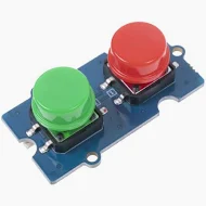
By now, you have got very good idea of how to connect new sensors to your MCU. Also how to start thinking about firmware by considering threads and how data is shared. Now is the good time to give you bit of freedom to test what you have learnt. You can now ask for a Grove dual button board. Shown below:
Note
Using the same approach as before, connect this onto Grove shield A2 and D2 ports on schematic. On silk screen you should see pin 2 and 3. Find out corresponding GPIO pins from schematic. Most probably its Pin 3 and Pin 4 but double check. Now add another thread to code you have written before to scan for button press. If Green button is pressed print H0 Started. If its pressed twice then say H0 is finished. Similarly, if Red is pressed then H1 is started. If its pressed twice then H1 is ended.
Think about the debounce time, the count for the button press etc. Use hacker and maker mindset and try few things on your own. To help you deal with the logic, see the flow graph and psuedo-code below:
Psuedocode is
Initialize:
    green_press_count = 0
    green_last_time = 0
    red_press_count = 0
    red_last_time = 0
    DEBOUNCE_MS = 200
    DOUBLE_CLICK_MS = 600

Forever loop:
    now = current_time_ms()

    # --- Green Button Logic ---
    if green_button transitions from HIGH → LOW:
        if (now - green_last_time) > DEBOUNCE_MS:
            green_press_count += 1
            green_last_time = now

    if green_press_count == 1:
        if (now - green_last_time) > DOUBLE_CLICK_MS:
            print("H0 started")
            green_press_count = 0

    if green_press_count == 2:
        print("H0 finished")
        green_press_count = 0

    # --- Red Button Logic ---
    if red_button transitions from HIGH → LOW:
        if (now - red_last_time) > DEBOUNCE_MS:
            red_press_count += 1
            red_last_time = now

    if red_press_count == 1:
        if (now - red_last_time) > DOUBLE_CLICK_MS:
            print("H1 started")
            red_press_count = 0

    if red_press_count == 2:
        print("H1 finished")
        red_press_count = 0

    Wait 50 ms
Solution
from machine import Pin, ADC
import time
import _thread
from my9221 import MY9221

# ---------------------------------------------------
# Hardware Connections (Verify from schematic)
# ---------------------------------------------------
# Grove LED Bar (MY9221): DI → GPIO6, DCKI → GPIO5
# Analog Sensor: Signal → GPIO1
# Grove Dual Button: A2 (GPIO3, Green), D2 (GPIO4, Red)
# ---------------------------------------------------

# --- LED Bar Setup ---
ledbar = MY9221(Pin(6), Pin(5))
ledbar.reverse(True)

# --- Analog Sensor Setup ---
analog_in = ADC(Pin(1))
analog_in.atten(ADC.ATTN_11DB)
analog_in.width(ADC.WIDTH_12BIT)

# --- Button Setup ---
green_button = Pin(3, Pin.IN, Pin.PULL_UP)  # A2 → GPIO3 (verify)
red_button = Pin(4, Pin.IN, Pin.PULL_UP)    # D2 → GPIO4 (verify)

# --- Shared Data ---
voltage = 0.0
lock = _thread.allocate_lock()

# --- State Tracking ---
green_pressed_time = 0
green_press_count = 0
red_pressed_time = 0
red_press_count = 0

# ---------------------------------------------------
# Thread 1: Sensor Reader
# ---------------------------------------------------
def sensor_task():
 global voltage
 while True:
     raw = analog_in.read()
     v = (raw / 4095) * 3.3
     with lock:
         voltage = v
     time.sleep(0.1)

# ---------------------------------------------------
# Thread 2: LED Display
# ---------------------------------------------------
def led_task():
 global voltage
 while True:
     with lock:
         v = voltage
     level = int((v / 3.3) * 10)
     ledbar.level(level)
     time.sleep(0.1)

# ---------------------------------------------------
# Thread 3: Button Handler (Green = H0, Red = H1)
# ---------------------------------------------------
def button_task():
 global green_pressed_time, green_press_count
 global red_pressed_time, red_press_count

 DEBOUNCE_MS = 200
 DOUBLE_CLICK_MS = 600

 last_green_state = 1
 last_red_state = 1

 while True:
     # -----------------------
     # GREEN BUTTON (H0)
     # -----------------------
     current_green = green_button.value()
     now = time.ticks_ms()

     if current_green == 0 and last_green_state == 1:  # Falling edge
         if time.ticks_diff(now, green_pressed_time) > DEBOUNCE_MS:
             green_press_count += 1
             green_pressed_time = now

     # Check if second press came quickly (double click)
     if green_press_count == 1:
         # First press detected -> Start timer
         if time.ticks_diff(now, green_pressed_time) > DOUBLE_CLICK_MS:
             print("H0 started")
             green_press_count = 0

     elif green_press_count == 2:
         # Second press within time window -> Finish
         print("H0 finished")
         green_press_count = 0

     # -----------------------
     # RED BUTTON (H1)
     # -----------------------
     current_red = red_button.value()

     if current_red == 0 and last_red_state == 1:  # Falling edge
         if time.ticks_diff(now, red_pressed_time) > DEBOUNCE_MS:
             red_press_count += 1
             red_pressed_time = now

     if red_press_count == 1:
         if time.ticks_diff(now, red_pressed_time) > DOUBLE_CLICK_MS:
             print("H1 started")
             red_press_count = 0

     elif red_press_count == 2:
         print("H1 finished")
         red_press_count = 0

     last_green_state = current_green
     last_red_state = current_red
     time.sleep(0.05)

# ---------------------------------------------------
# Start Threads
# ---------------------------------------------------
_thread.start_new_thread(sensor_task, ())
_thread.start_new_thread(led_task, ())
_thread.start_new_thread(button_task, ())

while True:
 time.sleep(1)
Collecting the Labelled Data
So far we have built basic framework for labelling the sensor data. When we press the green button, we can label the data as being collected under null hypothesis. When we click red button, we are collecting under alternative hypothesis. The final step is to store this data in a way that this can be analysed to implement the detection. It might be worth recalling the flow for implementing detection from lecture.
Currently, we are focusing on the first part of this workflow and you may realise that you have done all steps but the last one, i.e. storing/transmitting the data. For now, we will stream the data into the lab notes and create a file with appropriate label.
Firstly, you need to update the firmware on the MCU. All we now want to add is appropriate JSON messages. You can test the functionality in Thonny. Press green button it should start H0 data, then double press to stop. Now you can quit Thonny.
from machine import Pin, ADC
import time
import _thread
from my9221 import MY9221
import json

# ---------------------------------------------------
# Hardware Setup
# ---------------------------------------------------
ledbar = MY9221(Pin(6), Pin(5))
ledbar.reverse(True)

analog_in = ADC(Pin(1))
analog_in.atten(ADC.ATTN_11DB)
analog_in.width(ADC.WIDTH_12BIT)

green_button = Pin(3, Pin.IN, Pin.PULL_UP)  # H0
red_button = Pin(4, Pin.IN, Pin.PULL_UP)    # H1

# ---------------------------------------------------
# Shared Data & State
# ---------------------------------------------------
voltage = 0.0
lock = _thread.allocate_lock()

state = {"H0": False, "H1": False}

green_pressed_time = 0
green_press_count = 0
red_pressed_time = 0
red_press_count = 0

# ---------------------------------------------------
# Helper Functions
# ---------------------------------------------------
def send_json(obj):
    try:
        print(json.dumps(obj))
    except Exception:
        pass

def get_level(v, max_level=10):
    lvl = int((v / 3.3) * max_level)
    if lvl < 0:
        lvl = 0
    if lvl > max_level:
        lvl = max_level
    return lvl

# ---------------------------------------------------
# Thread 1: Sensor Reader
# ---------------------------------------------------
def sensor_task():
    global voltage
    while True:
        raw = analog_in.read()
        v = (raw / 4095) * 3.3
        with lock:
            voltage = v
            active_H0 = state["H0"]
            active_H1 = state["H1"]
        # Send data only if any hypothesis is active
        if active_H0 or active_H1:
            send_json({"data": round(v,4)})
        time.sleep(0.1)

# ---------------------------------------------------
# Thread 2: LED Display
# ---------------------------------------------------
def led_task():
    global voltage
    while True:
        with lock:
            v = voltage
        ledbar.level(get_level(v))
        time.sleep(0.1)

# ---------------------------------------------------
# Thread 3: Button Handler
# ---------------------------------------------------
def button_task():
    global green_pressed_time, green_press_count
    global red_pressed_time, red_press_count
    DEBOUNCE_MS = 200
    DOUBLE_CLICK_MS = 600
    last_green_state = 1
    last_red_state = 1

    while True:
        now = time.ticks_ms()
        # --- GREEN BUTTON (H0) ---
        current_green = green_button.value()
        if current_green == 0 and last_green_state == 1:  # falling edge
            if time.ticks_diff(now, green_pressed_time) > DEBOUNCE_MS:
                green_press_count += 1
                green_pressed_time = now

        with lock:
            if not state["H0"] and green_press_count == 1 and time.ticks_diff(now, green_pressed_time) > DOUBLE_CLICK_MS:
                state["H0"] = True
                green_press_count = 0
                send_json({"event":"H0_start"})

            elif state["H0"] and green_press_count >= 2:
                state["H0"] = False
                green_press_count = 0
                send_json({"event":"H0_end"})

        # --- RED BUTTON (H1) ---
        current_red = red_button.value()
        if current_red == 0 and last_red_state == 1:
            if time.ticks_diff(now, red_pressed_time) > DEBOUNCE_MS:
                red_press_count += 1
                red_pressed_time = now

        with lock:
            if not state["H1"] and red_press_count == 1 and time.ticks_diff(now, red_pressed_time) > DOUBLE_CLICK_MS:
                state["H1"] = True
                red_press_count = 0
                send_json({"event":"H1_start"})

            elif state["H1"] and red_press_count >= 2:
                state["H1"] = False
                red_press_count = 0
                send_json({"event":"H1_end"})

        last_green_state = current_green
        last_red_state = current_red
        time.sleep(0.05)

# ---------------------------------------------------
# Start Threads
# ---------------------------------------------------
_thread.start_new_thread(sensor_task, ())
_thread.start_new_thread(led_task, ())
_thread.start_new_thread(button_task, ())

while True:
    time.sleep(1)
- Make sure Thonny IDE is closed, as your serial port can only be connected to either your Browser or Thonny.
- Now click, Connect and select the COM port the board is connected to.
- Then press Start.
- Now if you press green button, and click on Raw Data Tab, you should see data flowing through.
- This data is also being added to the correct hypothesis in other tab. You can double check this.
- After 5 mins or so double click green button to stop collection of data.
- Start collecting data for H1.
- If you mess up any steps, just refresh and start over with the steps.
- Once done download H0 and H1 files.
- You will take this data in Google Co-lab for further analysis.
[]H₁:
[]
Google Co-lab and analysis
You need to have Google account for next steps. If you do not have one, setup an email account. Its free of cost and takes few minutes. Alternatively, if you are familiar with Jupyter Notebooks, you can use that as well. Head over to Colab URL: https://colab.research.google.com/
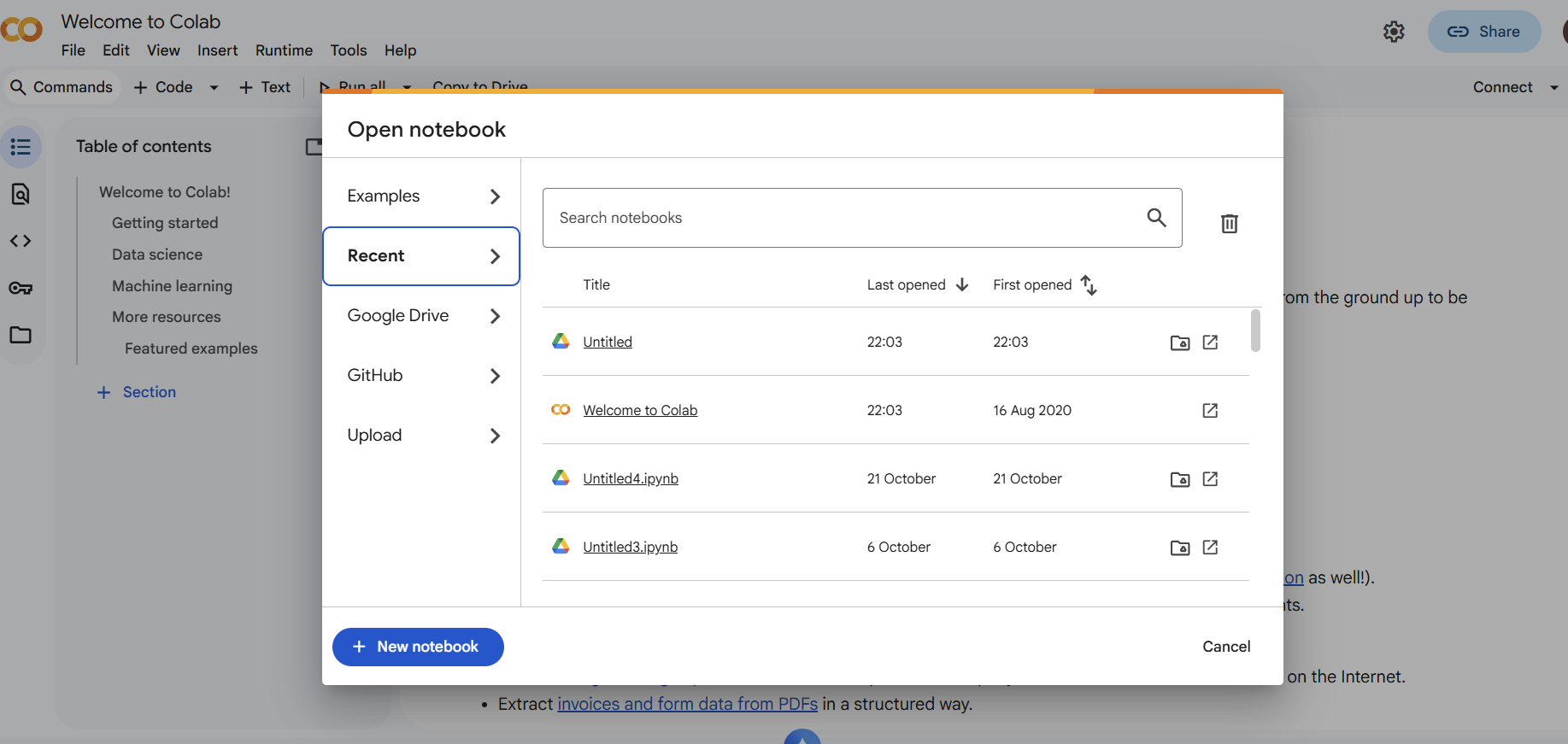
- Create new Notebook.
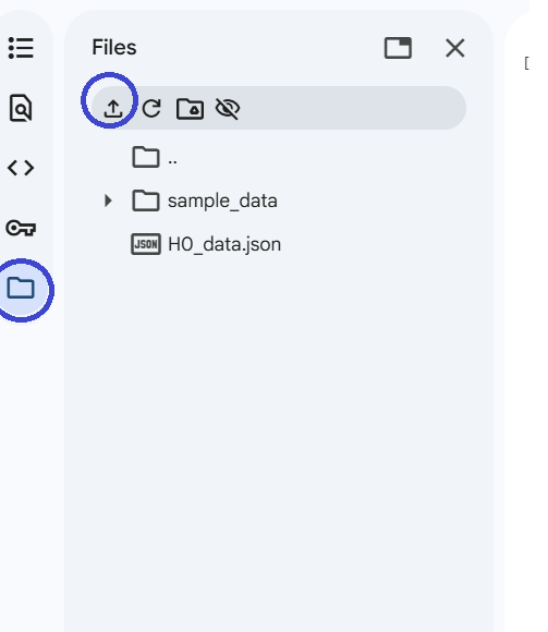
- Upload the data files into Co-lab workspace.
- Now write Python code to read files and plot histograms.
- Use the snippet below as a reference.
- The code also calculates the threshold for given false alarm rate on fitted Gaussian distribution.
- Now note this value and revisit our firmware to modify code, such that it declares each of the hypothesis using this threshold.
import json
import matplotlib.pyplot as plt
import numpy as np
from scipy.stats import norm

# -------------------------------
# Load H0 and H1 data
# -------------------------------
with open('/content/H0_data.json', 'r') as f:
    h0_data = json.load(f)

with open('/content/H1_data.json', 'r') as f:
    h1_data = json.load(f)

# -------------------------------
# Compute basic statistics
# -------------------------------
mean_h0 = np.mean(h0_data)
std_h0  = np.std(h0_data)
mean_h1 = np.mean(h1_data)
std_h1  = np.std(h1_data)

print(f"H0 mean: {mean_h0:.4f}, std: {std_h0:.4f}")
print(f"H1 mean: {mean_h1:.4f}, std: {std_h1:.4f}")

# -------------------------------
# Optional filtering thresholds
# -------------------------------
threshold_h0_filter = 0.4 * mean_h0
threshold_h1_filter = 0.4 * mean_h1

filtered_h0 = [x for x in h0_data if x >= threshold_h0_filter]
filtered_h1 = [x for x in h1_data if x <= threshold_h1_filter]

mean_filt_h0 = np.mean(filtered_h0)
std_filt_h0  = np.std(filtered_h0)
mean_filt_h1 = np.mean(filtered_h1)
std_filt_h1  = np.std(filtered_h1)

# -------------------------------
# Neyman-Pearson threshold for PFA
# -------------------------------
pfa = 0.05  # desired false alarm rate

# Right-tailed test (H1 if X > threshold)
# The Pfa is always calculated on H0 but in our case the role is reversed so we will calculate accordingly and then swap labels in the inference code
threshold_np = norm.ppf(1 - pfa, mean_filt_h1, std_filt_h1)
print(f"NP threshold for PFA={pfa}: {threshold_np:.4f}")

# -------------------------------
# Plotting
# -------------------------------
x = np.linspace(
    min(min(filtered_h0), min(filtered_h1)) - 0.1,
    max(max(filtered_h0), max(filtered_h1)) + 0.1,
    1000
)

pdf_h0 = norm.pdf(x, mean_filt_h0, std_filt_h0)
pdf_h1 = norm.pdf(x, mean_filt_h1, std_filt_h1)

plt.figure(figsize=(12,7))
plt.hist(filtered_h0, bins=30, alpha=0.6, density=True, color='skyblue', label='Filtered H0 Data')
plt.hist(filtered_h1, bins=30, alpha=0.6, density=True, color='salmon', label='Filtered H1 Data')

plt.plot(x, pdf_h0, 'b-', linewidth=2, label='Fitted Gaussian (H0)')
plt.plot(x, pdf_h1, 'r-', linewidth=2, label='Fitted Gaussian (H1)')

# Draw NP threshold
plt.axvline(threshold_np, color='k', linestyle='--', linewidth=2, label=f'NP Threshold (PFA={pfa})')

plt.title("Histograms with Fitted Gaussian and NP Threshold")
plt.xlabel("Value")
plt.ylabel("Density")
plt.legend()
plt.grid(True, linestyle='--', alpha=0.6)
plt.show()
Now when you print your threshold for given , you can modify the main.py for inference as follows:
from machine import ADC, Pin
import time

# ---------------------------------------------------
# Hardware Setup
# ---------------------------------------------------
analog_in = ADC(Pin(1))
analog_in.atten(ADC.ATTN_11DB)
analog_in.width(ADC.WIDTH_12BIT)


THRESHOLD_PFA = 0.0342


# ---------------------------------------------------
# Helper
# ---------------------------------------------------
def get_voltage():
    raw = analog_in.read()
    return (raw / 4095) * 3.3

# ---------------------------------------------------
# Main loop: sensor reading & hypothesis
# ---------------------------------------------------
while True:
    v = get_voltage()

    if v >= THRESHOLD_PFA:
        print(f"H0: {v:.3f} V")  # above threshold → H1
    else:
        print(f"H1: {v:.3f} V")  # below threshold → H0

    # else: do not print anything if voltage is between thresholds

    time.sleep_ms(100)
Conclusion and Follow On
In this lab, we have completed end-to-end implementation of the event detection through light sensor. You have learnt some basics for implementing and analysing such solution. So far, we have use wired connectivity over USB to gather data. Our next labs will focus on wireless transmission of these signals. As a follow on there are few activites for you to try:
-
ESP NOW is a very low power long range peer-to-peer communication protocol. Form a team of two people and try if you can implement ESP NOW transmission between the controllers to exchange either raw sensor values or the hypothesis. Implement AND and OR rule of network detection as discussed in lecture.
-
The ambient light sensors can be used to perform gesture recognition. Read this paper and check if you can do something similar with one sensor? [Paper]