
Lecture 9
Contents
- Modern Edge Application Development Tools and Lifecycle
- 1. Recap: Edge Computing as a Layered Abstraction
- 2. From Conceptual Layers to Operational Reality
- 3. Edge Hardware and Operating Systems
- 4. The Need for Portable and Reproducible Software
- 5. Toolset--Containers, Docker, Kubernetes and Microservices
- 6. The Build–Ship–Run Lifecycle
- 7. Orchestration: Managing Containers at Scale
- 8. Edge Middleware
- 9. Edge Applications
- 10. Cloud Integration
- 11. End-to-End Operational Architecture
- 13. Observability and Continuous Evolution
- 15. Summary
- References
Modern Edge Application Development Tools and Lifecycle
From Layered Abstractions to Operational Edge Architectures
1. Recap: Edge Computing as a Layered Abstraction
In the previous lecture, edge computing was introduced using a layered abstraction model. This model divided the edge ecosystem into conceptual layers, each representing a category of responsibility rather than a specific technology. Starting from physical hardware at the bottom and extending up to cloud and enterprise integration at the top, the layered model allowed us to reason about what functions must exist in any edge computing system.
The strength of this abstraction lies in its ability to separate concerns. Hardware engineers, system designers, application developers, and cloud architects can all reason about the same system without needing to understand every detail at once. However, abstraction also hides complexity. The model does not tell us how these layers are implemented, how software moves between them, or how systems are operated over time.
This lecture builds directly on that abstraction and explains how the layers are realised in practice using modern development tools and operational workflows.
2. From Conceptual Layers to Operational Reality
In real deployments, edge systems must be built, deployed, updated, monitored, and repaired continuously. A purely conceptual model is insufficient to explain how these activities occur. For example, knowing that an “application layer” exists does not explain how application code reaches thousands of geographically distributed devices or how updates are rolled out safely.
Operational reality introduces constraints that abstractions hide. Edge devices are resource-constrained, connectivity is unreliable, and physical access is limited. As a result, edge systems require automation, standardisation, and strong separation between development and deployment.
This lecture therefore shifts perspective: from what the layers are to how those layers are implemented and connected through tooling and lifecycle processes.

Figure 2: Mapping layered abstraction to operational flow of edge computing responsibilities.
On the left, we see the same layered abstraction from the previous lecture. Nothing has changed there — those responsibilities still exist. On the right, we see how each abstract layer is realised using concrete tools.
The key idea is that tools like Docker and Kubernetes do not replace layers — they instantiate them. We will learn a bit more about these tools in this lecture.
3. Edge Hardware and Operating Systems
At the base of any edge system lies the hardware and operating system layer. This includes processors (CPUs, GPUs, NPUs), memory, storage, sensors, actuators, and network interfaces. The operating system, typically a Linux variant or an RTOS, manages hardware resources and provides fundamental services such as scheduling, memory management, and device drivers.
Crucially, this layer has no understanding of applications, services, or data meaning. It provides execution capability but no semantics. From the perspective of higher layers, hardware and OS represent a pool of compute resources that must be managed efficiently and safely.
This limitation motivates the need for higher-level abstractions that can organise software execution in a portable and repeatable way.
4. The Need for Portable and Reproducible Software
Edge environments are inherently heterogeneous. Devices may differ in architecture, kernel versions, installed libraries, and available resources. Traditional approaches that rely on manually installing software or compiling applications directly on each device do not scale and are extremely difficult to maintain.
Reproducibility becomes a central concern. Developers need to ensure that the same application behaves identically across development machines, test environments, and deployed edge devices. This requirement leads to the concept of packaging applications together with their dependencies in a controlled manner.
Containers provide this packaging mechanism.
5. Toolset--Containers, Docker, Kubernetes and Microservices
Containers
Containers encapsulate an application along with its runtime environment, including libraries, language runtimes, and configuration files. Unlike virtual machines, containers do not include a full guest operating system. Instead, they share the host OS kernel, making them significantly more lightweight. Because containers reuse the host kernel, they are extremely lightweight. Starting a container is essentially the same as starting a normal process, which means containers can start in milliseconds. They also consume far less memory and storage than virtual machines. This makes them particularly suitable for cloud environments and edge devices where efficiency and fast startup are crucial. Conceptually, you can think of containers as standardized boxes that hold an application and everything it needs to run, except the operating system kernel.
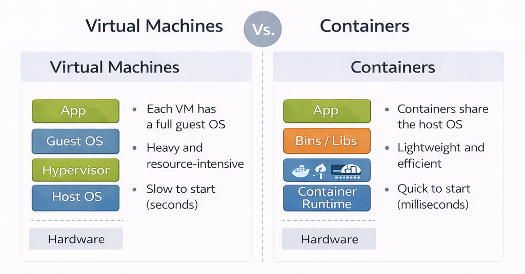
Figure 3: VMs vs Containers
Docker
Docker is often described as a container runtime, but more accurately, Docker is a toolchain that helps developers build, package, and distribute containerized applications. Docker standardizes how containers are built and distributed. At the center of Docker is the idea of a container image. A container image is a static, immutable artifact that contains application code, runtime libraries, and configuration defaults. It does not contain a kernel. This is why the same image can run on a laptop, a cloud server, or an edge device, as long as they share a compatible operating system kernel. Docker images are created using a text file called a Dockerfile, which describes how to assemble the image step by step. Each step creates a new layer, allowing images to be reused and cached efficiently.
Docker is the most widely adopted container platform and provides tools for building, distributing, and running containers. Using a Dockerfile, developers declaratively specify how an application environment should be constructed. The result is a container image that can be versioned, tested, and reused.
For edge computing, Docker offers two key advantages: portability across heterogeneous devices and reduced operational complexity. Once an image is built, it can run anywhere that supports Docker, independent of the underlying hardware details.
Kubernetes
Kubernetes is a distributed system designed to manage containerised workloads. On a single machine, Docker itself can start the container. However, it does not handle coordination, recovery, or scaling across many machines. Kubernetes adds a control plane that is capable of doing this. It schedules containers, monitors their health, handles restarts, and ensures that the system converges towards a desired state defined by configuration. This makes Kubernetes a container orchestration platform, responsible for coordinating and managing containers as a unified system at scale.
Microservices
With containers and orchestration in place, applications can be decomposed into microservices. Each microservice implements a small, well-defined function and runs independently in its own container.
This architectural style improves scalability, fault isolation, and maintainability. Failures in one microservice do not necessarily bring down the entire application. At the edge, microservices also allow selective deployment based on device capabilities.
1. Microservice Architecture (Application Design)
User Service
- Authentication
- Profiles
- Node.js + MongoDB
Payment Service
- Payments
- Refunds
- Python + PostgreSQL
Notification Service
- SMS
- Go + Redis
Analytics Service
- Tracking
- Reports
- Java + Kafka
2. Docker Containers (Packaging & Isolation)
User Service
Node.js Runtime
Dependencies
Payment Service
Python Runtime
Dependencies
Notification Service
Go Runtime
Dependencies
Analytics Service
Java Runtime
Dependencies
3. Docker Platform (Container Runtime)
Docker Engine
- Build images
- Run containers
- Networking & volumes
- Resource limits
- Image registry
4. Kubernetes (Container Orchestration at Scale)
Kubernetes Control Plane
- API Server
- Scheduler
- Controller Manager
- etcd
Worker Node 1
Worker Node 2
-
Microservices structure software, the containers package it and the orchestration manages its execution. The diagram below summarized the tool chain and effectively shows how microservices are an architectural pattern, containers are the packaging mechanism, Docker is the platform that makes individual containers work and Kubernetes manages it all. It has four sections.
-
Microservice Architecture on top demonstrates the architectural pattern of decomposing applications into independent services. As an example, it shows 4 different microservices (User, Payment, Notification, Analytics) belonging to a typical modern application. Each service has different technology stacks (Node.js, Python, Go, Java). They communicate via REST APIs.
-
Docker Containers in the middle shows how each microservice is packaged into its own container. Each container includes:
- The microservice code
- Runtime environment (Node.js, Python, etc.)
- All dependencies and libraries
-
Containers provide isolation, portability, and consistency. Dashed borders represent container boundaries.
-
Docker Platform is the container runtime engine that builds and runs individual containers
- Responsibilities:
- Building container images from Dockerfiles
- Running containers from images
- Managing container lifecycle (start, stop, restart)
- Network isolation between containers
- Resource limits (CPU, memory)
- Volume management for persistent data
- Image registry for storing and distributing images
- Scope: Operates on a single host/machine
- Responsibilities:
-
Kubernetes manages containers at scale across multiple machines
- Control Plane: The "brain" that makes decisions
- API Server: Entry point for all commands
- Scheduler: Decides which node runs which pod
- Controller Manager: Maintains desired state
- etcd: Stores all cluster configuration and state
- Worker Nodes: Physical or virtual machines that run the containers
- Node 1 and Node 2 shown with multiple pods. Each pod can contain one or more containers
- Key capabilities:
- Auto-scaling: Automatically add/remove containers based on load
- Self-healing: Restart failed containers automatically
- Load balancing: Distribute traffic across containers
- Rolling updates: Update services without downtime
- Service discovery: Containers can find and communicate with each other
- Secret management: Securely store passwords and keys
- Control Plane: The "brain" that makes decisions
6. The Build–Ship–Run Lifecycle
Docker enables a standardised build–ship–run lifecycle that underpins modern edge application development.
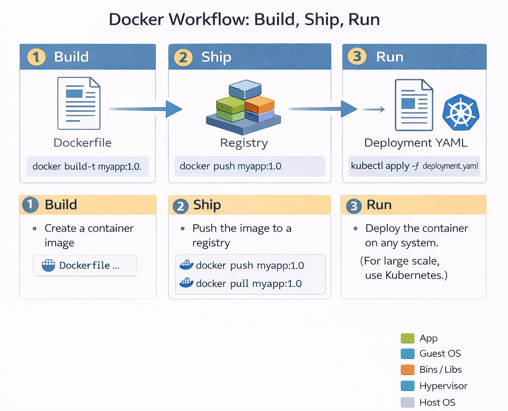
Figure 5: Build–Ship–Run lifecycle for containerised applications.
Build-Shihp-Run is not just a slogan; it represents a fundamental shift in how software is delivered. Modern software is delivered using a model where applications are built once, shipped as immutable images, and run consistently across cloud, edge, and embedded systems. This lifecycle decouples development from deployment. Developers focus on building images, while operations teams focus on running them. Importantly, the lifecycle is cyclical: observations made during runtime feed back into future builds, enabling continuous improvement.
Build
During the build phase, application code is compiled and packaged into a container image. This typically happens on a developer’s machine or in a continuous integration system. Once built, the image becomes a portable artifact that behaves the same everywhere. This step is typically performed using Docker. During the build process, the developer explicitly specifies all dependencies, runtime libraries, and system-level requirements needed for the application to execute correctly. The resulting container image encapsulates not only the application logic but also the assumptions under which the application is expected to run. It is an immutable image. "Immutable" means it cannot be changed once it is built; if you want to change one line of code, you must build a brand-new image.
From a theoretical perspective, the build phase defines the execution environment of the application. By fixing this environment, containers reduce variability across deployment targets, allowing the same image to run consistently on a developer’s laptop, in a cloud data centre, or on an edge device. This abstraction is a key reason containers have become fundamental to modern distributed systems.
Ship
The ship phase is about distribution. Instead of copying binaries or installers, the container image is pushed to a container registry. A registry acts like a versioned warehouse for images that allows images to be retrieved by runtime systems at any location. This is what enables large-scale deployments and over-the-air updates, especially in edge systems. Importantly, shipping the image separates application development from application deployment. This phase decouples development from deployment. The developer doesn't need to know which specific edge device will run the code; they only need to put the image in the warehouse where the device can find it. Developers no longer need direct access to production systems; instead, they publish images that can be independently pulled and executed by orchestration platforms.
This decoupling introduces a clear boundary between what the application is and where it runs. From a systems viewpoint, this enables scalable deployment across geographically distributed infrastructures, including edge environments where direct manual deployment would be infeasible. During the ship phase, this image is distributed through a container registry. Instead of copying binaries or installers, the container image is pushed to a container registry. A registry acts like a versioned warehouse for images that allows images to be retrieved by runtime systems at any location. This is what enables large-scale deployments and over-the-air updates, especially in edge systems. Importantly, shipping the image separates application development from application deployment. Developers no longer need direct access to production systems; instead, they publish images that can be independently pulled and executed by orchestration platforms.
This decoupling introduces a clear boundary between what the application is and where it runs. From a systems viewpoint, this enables scalable deployment across geographically distributed infrastructures, including edge environments where direct manual deployment would be infeasible.
Run
During the run phase, the image is instantiated as a running container on an edge device. The run phase is where the image is actually executed. The edge device pulls the image from the registry and starts it. Because the image contains everything the app needs, it runs the same way on an edge gateway as it did on the developer's laptop.
7. Orchestration: Managing Containers at Scale
While containers solve the problem of packaging, they introduce new challenges at scale. Large edge deployments may involve hundreds or thousands of devices, each running multiple containers. Containers may fail, devices may disconnect, and updates must be applied consistently.
Manual container management does not scale under these conditions. An automated control layer is required to monitor system state, restart failed services, and enforce deployment policies. This requirement motivates container orchestration. This orchestration layer corresponds directly to the Edge Software Layer in the abstraction model.
Kubernetes at the Edge
In production systems, especially those involving many devices or many applications, the run phase is managed by Kubernetes, which is responsible for executing container images in a controlled and scalable manner. Rather than starting individual containers directly, Kubernetes operates using a declarative model. The developer or operator specifies the desired state of the system—such as how many instances of an application should be running—and Kubernetes continuously works to maintain that state.
Kubernetes monitors application health, restarts failed containers, and distributes workloads across available nodes. In this sense, Kubernetes acts as a feedback-driven control system that enforces correctness at runtime. It is useful to understand that Kubernetes does not simply “run containers”; it manages the ongoing execution of applications over time, adapting to failures and resource changes.
In edge environments, lightweight Kubernetes variants such as K3s and KubeEdge adapt the platform to resource-constrained and intermittently connected devices. Kubernetes effectively acts as an operating system for containers, abstracting away individual device management.
How are Containers Updated?
This is where the power of Kubernetes and the Declarative Model comes in. In a traditional system, you might "patch" a running program. In a modern edge system, you replace the entire container.
The "Desired State" Mechanism Kubernetes does not just "start" a program; it manages a Desired State.
-
The Instruction: You tell Kubernetes, "I want three instances of Traffic-App:v1.0 running".
-
The Update: When the data science team builds a better AI model, they ship Traffic-App:v2.0 to the registry.
-
The Trigger: You update your instruction to: "I want three instances of Traffic-App:v2.0 running."
The Replacement Process Once the instruction changes, Kubernetes automatically handles the transition:
-
Step 1: It "pulls" the new v2.0 image from the registry.
-
Step 2: It starts a new container using the v2.0 image.
-
Step 3: Once the new version is confirmed as "Healthy" (Running), Kubernetes shuts down and deletes the old v1.0 container.
-
Step 4: If the new version fails or crashes, Kubernetes can automatically "roll back" to the old version to keep the factory or city infrastructure running.
How Kubernetes Ensures Reliability Through Continuous Reconciliation
Kubernetes doesn't simply "start containers and hope they keep running"—it implements a continuous control loop that actively maintains system reliability. At the heart of this mechanism is the concept of desired state versus actual state. When you deploy an application, you declare your intent: "I want three instances of the analytics service running at all times." Kubernetes stores this declaration and continuously monitors reality to ensure it matches. Every few seconds, the Kubernetes control plane queries each container's status using health checks—lightweight HTTP requests or command executions that verify the application is responsive. If a container crashes due to a memory leak, fails to respond to health checks, or is killed by the operating system, Kubernetes immediately detects the deviation from desired state. Within seconds, it schedules a replacement container on an available node, pulls the same image version from the registry, and starts it with identical configuration. This happens automatically, without human intervention, even at 3 AM on a Sunday. In our factory scenario, if a vibration analysis microservice fails on one robotic arm's edge gateway, Kubernetes restarts it before the next sensor reading arrives, ensuring continuous monitoring with minimal data loss. This self-healing capability is why edge systems can maintain 99.9% uptime despite individual component failures—the system continuously repairs itself faster than failures can accumulate.
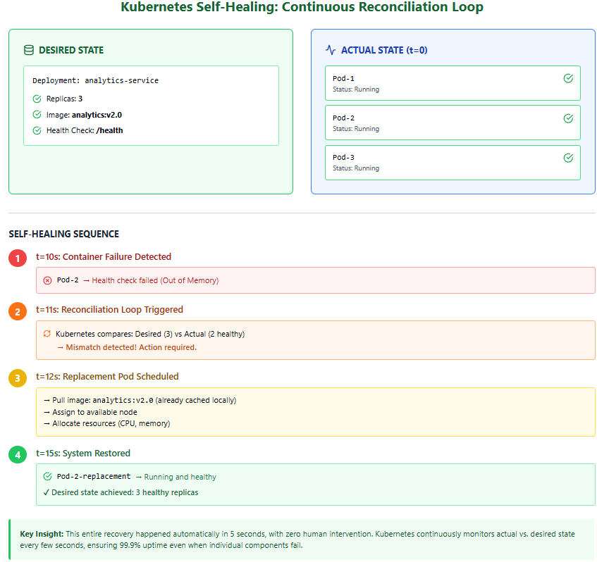
Figure 6: Kubernetes Self Healing: Continuous Reconciliation Loop
8. Edge Middleware
Containers and orchestration manage computation, but they do not understand physical devices, protocols, or data semantics. Edge middleware platforms, such as EdgeX Foundry, address this gap.
Middleware abstracts device communication, normalises data formats, manages event routing, and enforces security boundaries. It provides a stable interface between physical devices and application logic.
This layer maps directly to the Edge Middleware Layer from the abstraction model.
EdgeX Foundry: Solving the Proprietary Protocol Problem
In industrial environments, edge devices rarely speak a common language. A temperature sensor from one manufacturer might use Modbus RTU, while a vibration sensor uses MQTT, and a legacy pressure gauge communicates via a proprietary serial protocol. Without middleware, each application would need custom code to understand every device type, creating a maintenance nightmare that doesn't scale. EdgeX Foundry solves this by acting as a universal translator between devices and applications. At its core, EdgeX is itself a collection of containerized microservices that implement a standardized data model. Device-specific adapters (called "device services") handle the low-level protocol communication, converting raw sensor readings into a normalized JSON format that all applications can understand. For example, whether a temperature reading arrives via Modbus, BACnet, or a REST API, EdgeX transforms it into a standard event structure containing metadata, timestamps, and the value itself. Application microservices can then subscribe to these normalized events without ever needing to know which physical protocol was used. This abstraction is what allows the predictive maintenance algorithms in our manufacturing example to work identically across 15 factories, even though each factory may have purchased sensors from different vendors over different years.
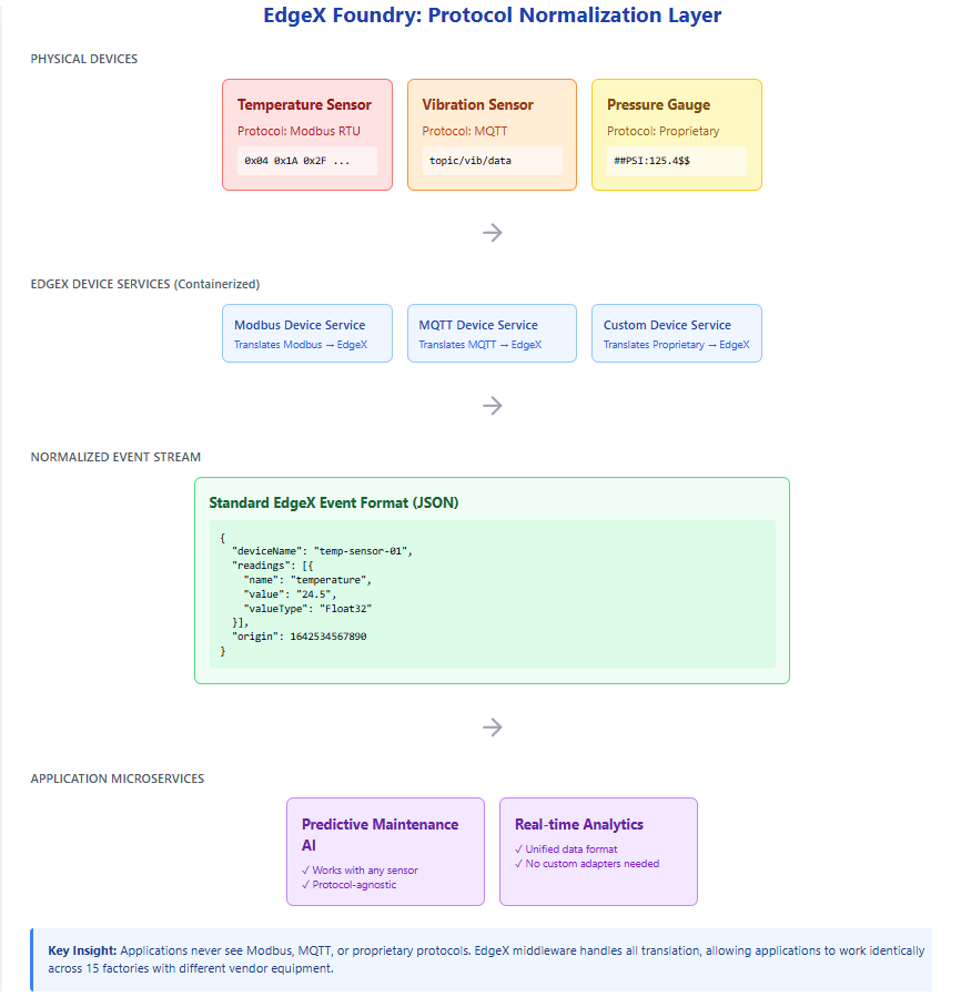
Figure 7: EdgeX Foundry: Protocol Normalization Layer
9. Edge Applications
Edge applications sit above middleware and implement domain-specific functionality. These may include AI inference services, real-time analytics pipelines, or control systems.
Applications are typically built from multiple microservices and deployed as containers managed by Kubernetes. They consume data from middleware rather than directly interacting with hardware, which improves portability and modularity.
10. Cloud Integration
The cloud plays a complementary role rather than acting as a central controller. It provides large-scale compute resources for tasks such as model training, long-term analytics, fleet management, and cross-site coordination.
This collaborative edge–cloud relationship corresponds to the Cloud and Edge Integration Layer of the abstraction model.
11. End-to-End Operational Architecture
All layers and tools can be combined into a single operational view that instantiates the conceptual abstraction.
This diagram should be understood as a concrete realisation of the layered model studied previously.
Resilience and the Offline Edge
While the Build–Ship–Run lifecycle assumes a continuous flow of data and images, edge environments are often defined by intermittent connectivity. Understanding how the lifecycle behaves when the "link to the cloud" is severed is critical for designing robust systems. The true test of an edge architecture is its behavior when connectivity to the cloud is severed. In traditional cloud-centric systems, a network outage would halt operations entirely—applications couldn't access their code, databases, or configuration. Edge computing inverts this dependency by ensuring all critical operational capabilities exist locally. When a factory's internet connection fails, the containerized applications continue running because the container images—containing all application code and dependencies—are already stored on local disk. Kubernetes continues managing these containers using its local control plane; it doesn't need to "phone home" to restart a failed service or enforce resource limits. EdgeX middleware continues normalizing sensor data and routing it to local analytics services. The AI models performing predictive maintenance execute their inference locally, and critical alerts can still be generated and acted upon. What stops during an outage is evolution, not operation. New container images cannot be pulled from the central registry, meaning software updates must wait until connectivity resumes. Similarly, the cloud cannot receive new training data, logs, or metrics, so model retraining and fleet-wide analytics are paused. When connectivity returns, the system automatically synchronizes: buffered telemetry uploads to the cloud, pending updates download to the edge, and the continuous improvement cycle resumes. This design ensures that a two-day internet outage might delay improvements to the system, but it never stops the factory floor from operating safely and effectively.
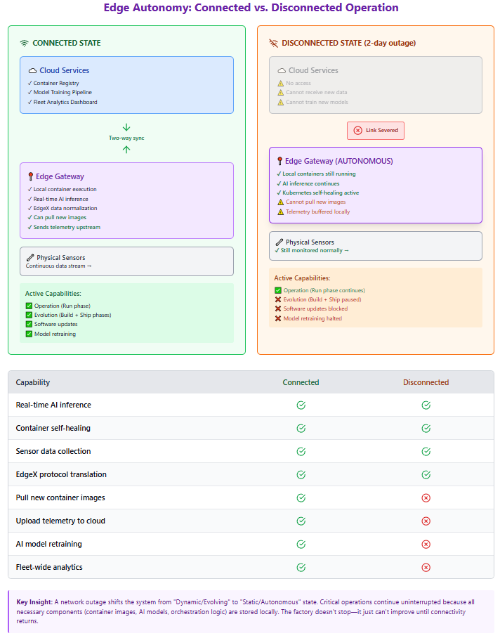
Figure 8: Edge Autonomy: Connected vs. Disconnected Operation
1. The Autonomous "Run" Phase
The primary advantage of the operational edge architecture is that the Run phase is decoupled from the Build and Ship phases.
Local Execution:
Because containers include all necessary dependencies and libraries, they do not need the internet to start or execute once they are physically present on the device.
Orchestration Stability:
Lightweight Kubernetes variants (like K3s or KubeEdge) are designed to manage the "desired state" locally. If a container crashes during an internet outage, Kubernetes will still restart it because the control logic exists at the edge site.
Middleware Continuity:
Middleware like EdgeX continues to normalize data from proprietary sensors and pass it to local microservices regardless of cloud status.
2. The Stalled Evolution Loop
While the edge remains operational, it ceases to be evolutionary during an outage. The "Continuous Evolution" loop is broken in two specific places:
The Inbound Gap (Ship):
New container images stored in the central registry cannot be "pulled" to the edge. This means security patches and algorithm updates are paused until connectivity is restored.
The Outbound Gap (Observe):
The observability feedback loop—consisting of logs, metrics, and high-value data for retraining—cannot reach the cloud. Consequently, the "Build" phase in the cloud is starved of new data, preventing the creation of improved AI models.
Note
This Replace, Don't Patch strategy is essential for edge computing for three reasons:
- Consistency: You never end up with "half-updated" software that causes weird bugs.
- Speed: Containers start in milliseconds, making updates very fast.
- Reliability: Since Kubernetes acts as a feedback-driven control system, it continuously monitors the health of these containers and restarts them automatically if they fail, even if the internet is down.
Note
In this architecture, an internet outage is not a system failure but a state degradation. The system moves from a Dynamic/Evolving State to a Static/Autonomous State. The goal of using tools like Docker and Kubernetes at the edge is to ensure that while the evolution might stop, the execution does not.
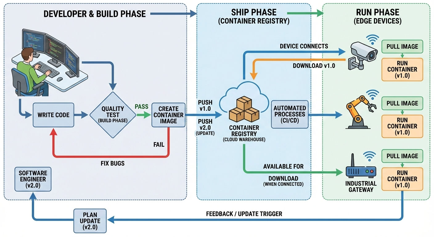
Figure 9: End to end development-operation cycle for edge applications
13. Observability and Continuous Evolution
Edge systems must evolve continuously. Observability mechanisms—logs, metrics, and traces—provide visibility into system behaviour.
This feedback loop connects runtime behaviour back to the build–ship–run lifecycle, enabling iterative improvement.
15. Summary
This lecture completed the transition from conceptual abstraction to operational understanding. By introducing Docker, Kubernetes, middleware, and the build–ship–run lifecycle, we showed how modern edge systems are built, deployed, and evolved in practice.
References
[1] Poulton, N. The Kubernetes Book. 2nd ed., O'Reilly Media, 2024.
[2] Menon, L., Ramamoorthy, G., & Nithyanandan, H. Edge Computing with Kubernetes (1 ed.) (2025). BPB Publications